Power Supply Test

A DC power supply is a device which transfers AC main power to a required DC output V/A/W rating. A good power supply should be reliable, meet all required functional specifications, full protection features, safety and Electromagnetic compatibility requirements. This application note is focusing on the testing of functional specifications and protection features.

Power supply testing methods for design, production, and quality verification require sophisticated electronic equipment. Different power supply configurations and output combinations also dictate the need for versatile test instruments that can accommodate a broad range of specifications.

Prodigit 3300 series Mainframe, 3310/3320 series Electronic Load Module, and 3600A power supply testers provides programmability, friendly operation, reliable test results, efficient testing and high testing quality at a minimal testing cost. Those instruments have been broad used to test the function of power supply by known manufacturer worldwide.

Following are functions typically tested when qualifying a switching power supply.

Function test:

Hold on adjust

Line Regulation

Load Regulation

Combined Regulation

Ripple and Noise or PARD

Input Power and Efficiency

Dynamic load or Transient load

Power Good/Power Fail (Power Good Signal)

Set-up/Hold-up time


Protection test:

Over Voltage Protection (OVP)

Over Current Protection (OCP)

Short Circuit Protection


1.1 Hold on adjust/set output voltage

When manufacturing switching power supplies, the first test step is to adjust output voltage to within a specified range. This is done first to ensure further specifications are met. Normally, the AC line voltage is set to nominal and the Dc output current is set to a nominal or a maximum load current in the HOLD-ON adjust procedure. The DVM measures the power supply's output voltage, and adjusts the potentiometer until the voltage reading is within the required limit.


1.2 Line Regulation

Line regulation is defined as a power supply's ability to provide a stable output voltage under conditions of changing input line voltage.

To accurately measure line regulation, the following equipment is required:

a. A variable line source capable of providing at least the minimum to maximum input range of the power supply to be tested.

b. A true RMS voltmeter to monitor the input source voltage.

c. A precision DC voltmeter with an accuracy at least 10 times better than the regulation of the unit under test.

d. A variable load for output.


Typically, the equipment is set up as shown below:
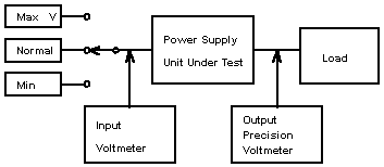


During testing, allow the power supply unit under test to warm up and stabilize with a normal input voltage and load, Output voltage reading should then be taken with low, normal and high line input. Output voltage reading from normal to low and high line conditions generate the Line regulation quality for that load condition. Line regulation is normally specified as a percentage of deviation from nominal output at a fixed load and is calculated using the following equation.


Line regulation can also be specified as the absolute DC output deviation within upper and lower voltage limit under changing input line voltage.

1.3 Load Regulation
Load regulation is a power supply's ability to provide a stable output voltage under conditions of changing load. Equipment and set-up required are very similar to that for line regulation. The only change required is the connection of an additional precision Ammeter in series to the output as illustrated below:
13_e02.gif

During testing, allow the power supply under test to warm up and stabilize, then measure the output voltage and use it as normal output voltage (Unormal). Additional output voltage reading are then taken with maximum (Umin) and minimum (Umax) loads on the output. Output voltage deviation from normal to full load and minimum load generate the Load regulation.

Load regulation is normally specified as a percentage of deviation from nominal output at a fixed input voltage and is calculated using the following equation:

13_c03.gif

Load regulation can also be specified as the absolute DC output reading within upper and lower voltage limit.

1.4 Combined Regulation
Combined regulation is a power supply's ability to provide a stable output voltage under conditions of changing line voltage and load current. It is a combination of line regulation and load regulation, and provides more exact verification of a power supply's DC output by changing line input and load output.
Combined regulation is specified as the absolute DC output deviation within upper and lower voltage limits under changing input line voltage and output load current.

1.5 Ripple and Noise or PARD
PARD is the periodic and random deviation of the DC output voltage from its average value over a specified bandwidth with all other parameter constant. It is representative of all undesirable AC and noise components remaining in the DC output voltage after regulation and filtering.

13_c04.gif

PARD consists of Undesirable signals superimposed on the DC output of a power supply.
PARD is measured normally in Peak to Peak values, and is typically specified over a bandwidth range from 20Hz to 20MHz. Any deviation below 20Hz is included in a specification called output drift. 
To make PARD measurements, an Electronic Load should have lower PARD than the power supply being tested. A regulated AC source should be applied to the input of the power supply under test. PARD measurements are made at the lowest and highest specified value of AC input to the power supply. Proper connection between the instruments and power supply under test are essential when making these measurements since PARD consists of low level, wide band signals. Major test concerns are ground loops, proper shielding, and impedance matching. An oscilloscope can be used for peak to peak measurements, to eliminate cable ringing and standing waves. The typical configuration includes coaxial cabling with 50£[ terminational both ends. Capacitors should be connected in series with the signal path to block the DC current. It should use instruments with floating (differential amplifier) input to eliminate Ground Loop problem between power supply and testing equipments.

Prodigit 3310/3320 series and 3600A DC Electronic Load has a low PARD which is suitable to test the PARD of a power supply, the 4030 and 3600A PARD measurement has a differential 50£[ impedance input circuit configuration, it can measure up to four output PARD simultaneously.

1.6 Input Power and Efficiency
The efficiency of a power supply is the ratio of its total output power to its total input power. For a typical AC to DC power supply, the input power must be true power or average power, not just Vrms x Arms.
13_c05.gif

The formula for efficiency is:
13_c06.gif

Power supply efficiency provides verification of correct operation. If efficiency is outside the specified range there is either a design flaw or a problem with the individual unit.
Efficiency should be measured under steady - state operation after the unit’s been allowed to warm up.
For some power supplies, efficiency is a function of loading. In this case, the load should be varied to provide ample data to plot effective test results.
The 3600A testers, measures efficiency utilizing their AC source electronic loads. True power measurement circuitry requires adequate time to read the DC load. Allow for more setting time to get stable readings when changing input. As for PARD measurements, normally needs more time than DC load V/A, as a result, needs more setting time to get stable reading when large input power is changed. Please use the same rule as described in PARD measurement: set Tmeas.n to higher value (for example: 2 sec.) to get a stable PARD reading rather than to lower Tmeas.n value which would result in an unstable PARD reading. Finally, add a reasonable Tmeas.n margin (for example 20% or more) to get stable readings at every measurement. Taking these steps will provide stable and accurate reading with a minimum of testing time.

1.7 Dynamic load or Transient Load
A constant voltage output DC power supply is designed with a feedback loop which continuously maintains the output voltage at a steady-state level. The feedback loop has a finite bandwidth which limit the ability of the power supply to response to a change in the load current. If the phase shift between the loop input and output is 180 degree at its unity gain crossover, the power supply will become unstable and oscillate.

13_c07.gif

Typically, loads are dynamic rather than exhibiting a steady state current. (For example: a Hard/Floppy disk drive, CPU, RAM etc. draws higher current on start up.) Therefore, dynamic response testing is very important when testing a power supply. The dynamic load can emulate the worst case real world load for testing a power supply, such as High/low load period, Rise/Fall slew rate, and High/Low load level. If a power supply can pass dynamic load testing in accordance with its output specifications and not to generate overshoot/undershoot on its output voltage then it is considered good.

Steps for setting the Dynamic Loading:
1.Using an oscilloscope to measure the actual load current wave form in your system (computer, printer, etc.) and record each real dynamic load current. 
2.Using setting to simulate the worst case dynamic load current wave forms to the test power supply. For a step load current change, a marginally stable power supply will have a ringing voltage output, this could be damage voltage sensitive loads, such as logic circuitry in a computer. Step load current response testing checks critical test points, such as defective output filter, capacitor or loose capacitor connection etc.

1.8 Power Good/Power Fail (Power Good Signal)
The Power Good Signal (PGS) is a signal sent to a computer system to indicate that the specified power was provided after output became stable. The Power Fail Signal indicates the power supply's output is dropped below or reaching before the specified output. This is normally indicated as a logic level change; logic 1, or high, equals power good; logic 0 or low, equals power fail.
Please see below figure:

13_c08.gif

Prodigit 3600A testers can measure the power good and power good time duration with programmable threshold voltage for load 1 (main) output and power good signal. They also check for ring or unstable conditions for the power good signal. Prodigit 3600A has a capability to measure the Timing of Power Good and Power Fail. It has programmable Logic level and output voltage level.

1.9 Set-up/Hold-up time
A Set-up time is the duration from turn the power supply input ON until its output voltage goes up into a regulated limit. For example of a 5V output power supply, Set-up time is from turn input ON to output voltage up to 4.75V. A Hold-up time is a duration from turn the power supply input OFF until its output voltage goes down into an unregulated limit. For example of a 5V output power supply, Hold-up time is from turn input OFF to output voltage down to 4.75V. Prodigit 3600A has the ability to measure the set-up time and hold-up time of a power supply, it has programmable output voltage level. The timing relationship of Set-up time and Hold-up time is shown below:

13_c09.gif

2.1 Over voltage
A power supply is expected to shut down its output voltage if it exceeds the maximum specified voltage. The over voltage protection test demonstrates the ability of a power supply to correctly response to any of these conditions.
The over voltage protection feature is very important for sensitive loads such as CPU, Memory, and logic circuitry, etc. Permanently damage will result if operating voltage exceeds the specifications for a component.

13_e10.gif

Prodigit 3600A Power Supply Testers can test and measure a power supply's OVP for both functional and actual over voltage readings. They require an optional external DC source to trigger the OVP circuitry in closed-frame power supplies.

2.2 Over Current Protection
A power supply is expected to shut down or limit its output current without damage to itself or external circuits prior to exceeding specified limits. This shut down should also occur to avoid damage to a power supply that could be caused by defective components which can cause the supply to draw more current than normal. The over current protection test demonstrates the ability of a power supply to correctly response to any of these conditions.
Prodigit 3600A power supply testers can test and record readings at each output for the power supply under test. The load current will increase from a predetermined current until the output voltage drops to the programmed threshold voltage limit.

2.3 Short Circuit Protectionn
A power supply is expected to shut down or limit output current without damage if its output is shorted to ground. The short circuit protection test demonstrates the ability of the power supply under test to correctly response to any short circuit conditions.
All Prodigit 3310/3320 series Electronic Loads has a built-in short circuit function key. The 3600 series power supply tester also have a built-in short circuit protection function test. This allows for short voltage and short current reading when performing the short circuit test.

Please leave information for advice