New features of electronic load Prodigit Seri 3310G
- 12/06/2023
Prodigit develops the latest 3310G Series electronic loads.
The 3310G is a highly upgraded version of the successful 3310G series electronic load family.
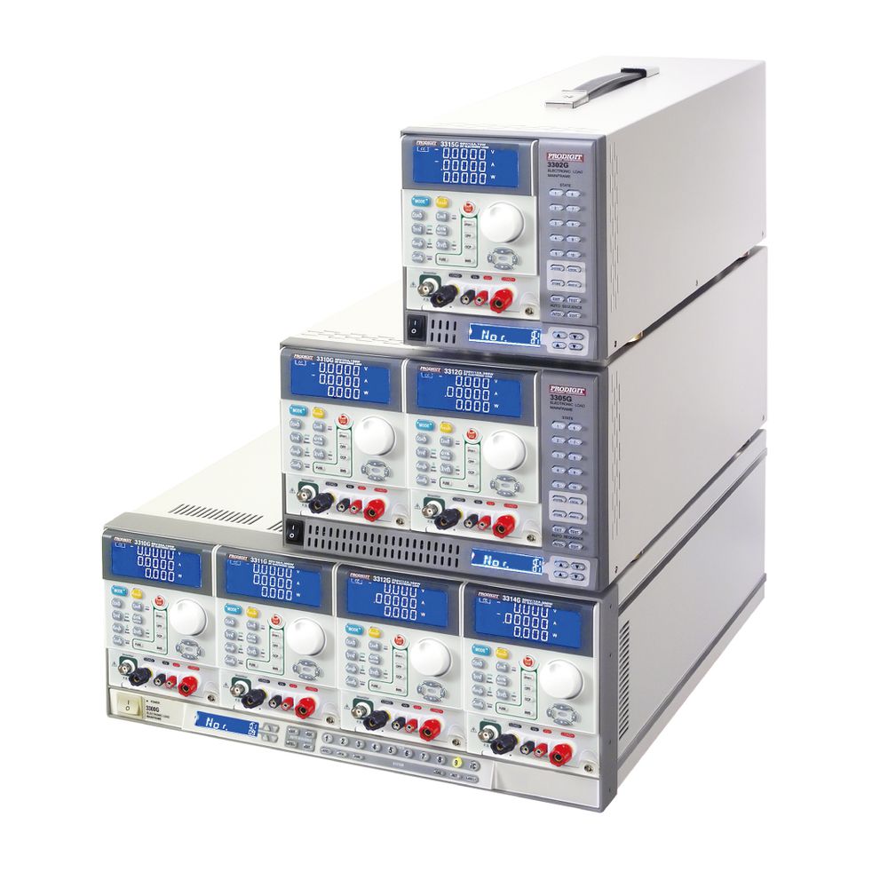
The 3310G Series consist of the following models:
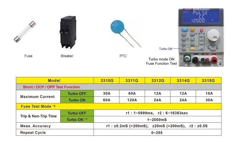
- 3310G (60V/ 30A, 150W)
- 3311G (60V/ 60A, 300W)
- 3312G (250V/ 12A, 300W)
- 3314G (500V/ 12A, 300W)
- 3315G (60V / 15A, 75W)
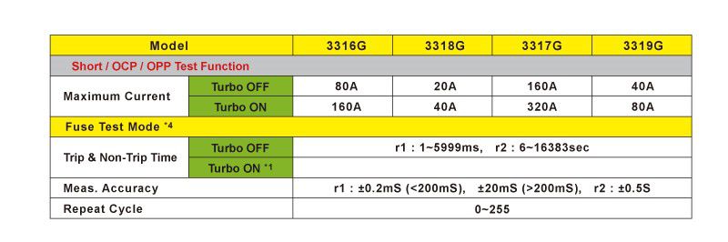
- 3316G (80V / 80A, 100W)
- 3317G (80V / 160A, 800W)
- 3318G (500V / 20A, 400W)
- 3319G (500V / 40A, 800W)
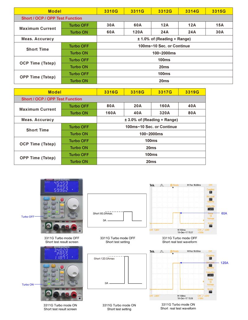
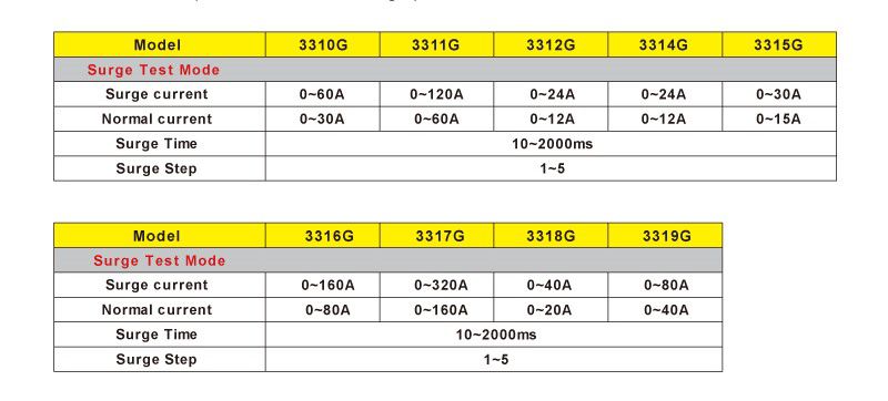
The model table below highlights the different power and current capabilities for each model.
Model list of 3310G Series Electronic Load with Turbo mode.
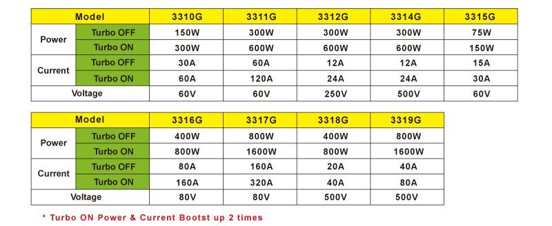
Turbo mode is very valuable for enhanced protection testing of power products. Examples include power supplies, Battery Management Systems (BMS) and protection devices such as Fuses / Breakers or PTC Resettable fuses. In doing so, the 3310G Series can test and verify the actual trip current levels and response times under abnormal operating conditions.
The current can be increased by 2 times during the test which can improve the test current shortage of electronic load.
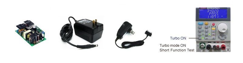
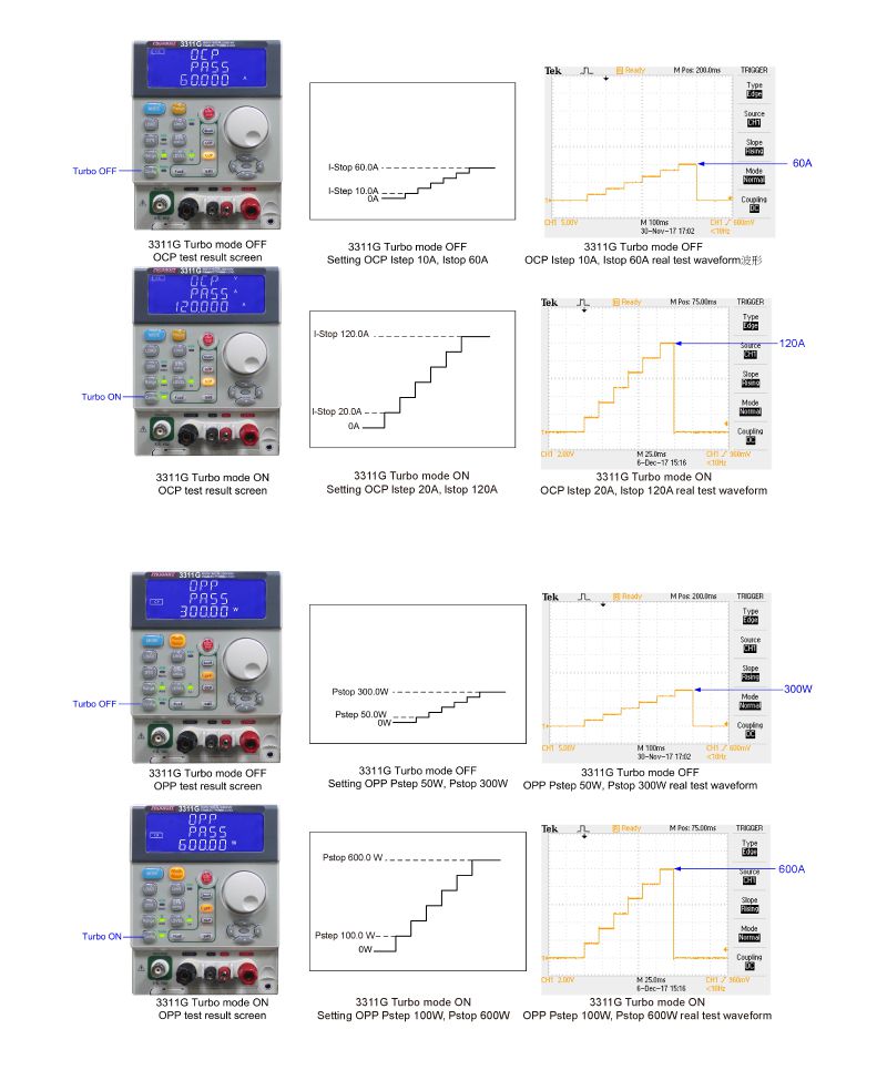
The built-in test functions for Turbo mode include Short, OCP, OPP, BMS and Fuse tests.

The following example illustrates the ease of performing these kinds of tests with the 3310G Loads.
1. Turbo mode ON/OFF indicator, Turbo mode includes Short, OCP, OPP, BMS, Fuse test functions, the other new functions are MPPT with CC and CR mode, CV response time setting, Battery discharge Batt1 ~ Batt3 in Config key.
2. Fuse (Current Protection Components) Test function key.
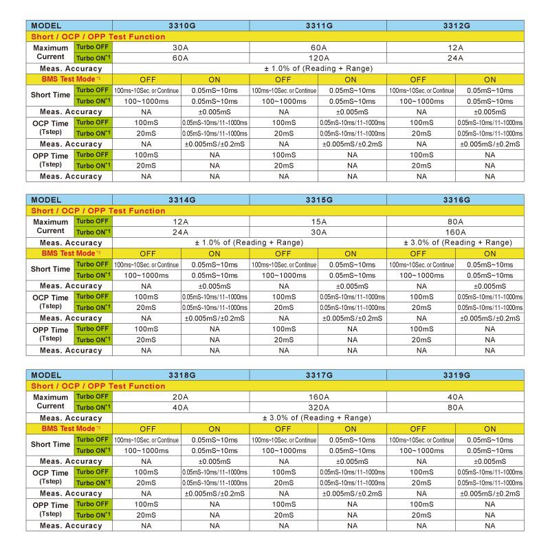
3. BMS (Battery Management System) test mode key.
4. Add CC+CV and CP+CV for battery discharge test.
1. Overload Protection Testing of power supplies
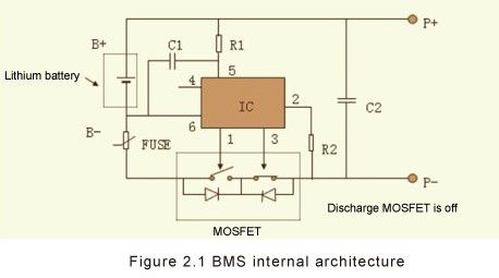
2. BMS Protective Devices
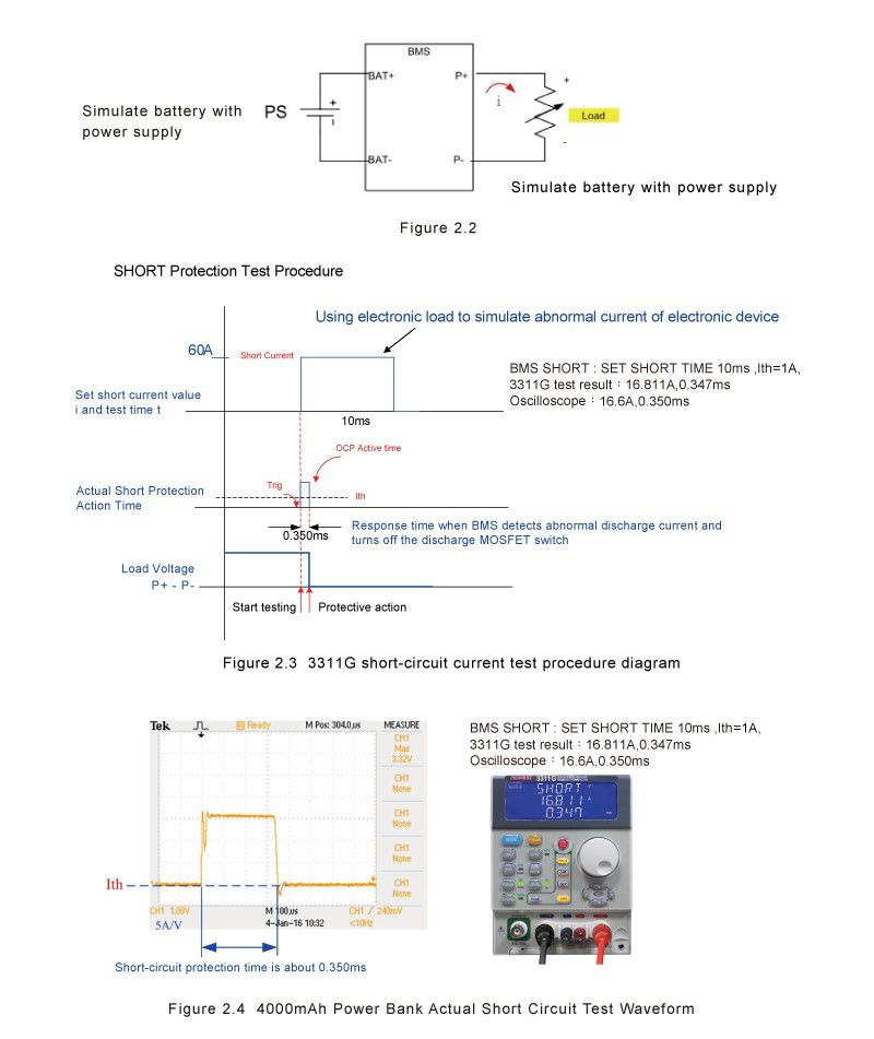
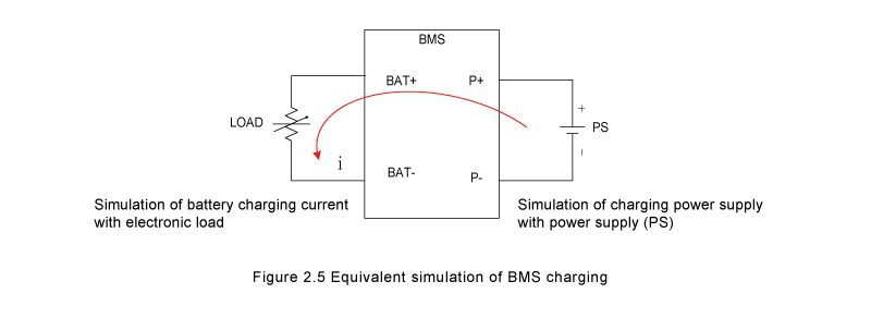
Power supply (PS) & LOAD connection is shown in Figure 2.1, LOAD test procedure is shown in Figure 2.3.
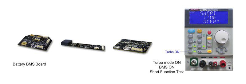
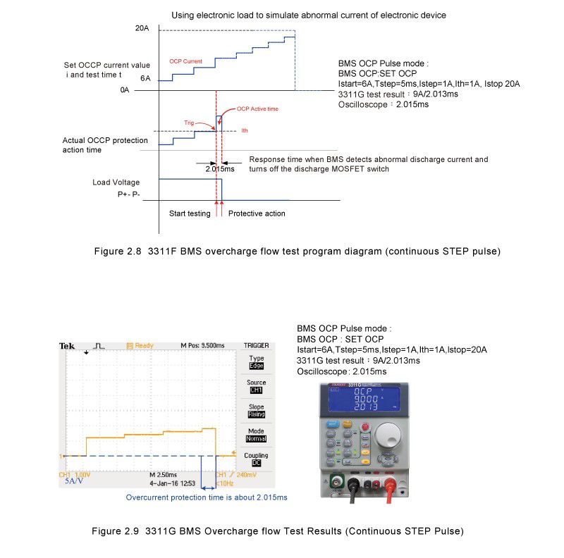
The test method is divided into single pulse and continuous step pulse. Single pulse can be used for rapid tests. It can be used for a large number of fast tests suitable for the production line. Continuous step pulse can be used to scan the actual over current protection point. Suitable for research and development that needs accurate point. The power supply (PS) & LOAD connection and test procedures are shown in Figure 2.5.
2.4 Overcurrent discharge protection (OCDP) test method: Power supply (PS) & LOAD connection and test procedures are shown in Figure 2.10.
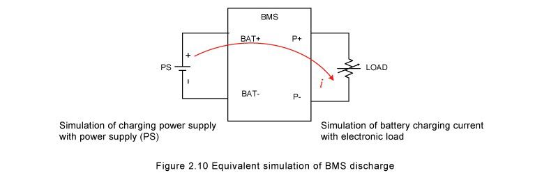
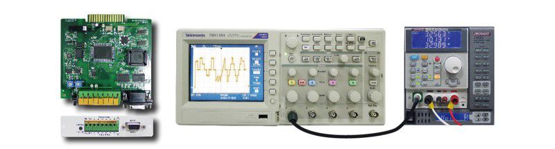
The battery BMS can immediately provide protection and disconnection measures for the abnormal voltage, current, temperature and other conditions of the battery to avoid the occurrence of danger; because the battery BMS is a safety measure that must be 100% full-featured test verification that security can be ensured. Although the test and verification for the battery BMS can use the oscilloscope to measure the current value and action response time of the BMS action, it is undoubted that the oscilloscope can be tested in detail during the development stage. But in a mass production stage, there is a need for rapid and complete testing and there is a limit on capacity production. For this difficulty, Prodigit integrates the BMS test into the 3310G series electronic load. In addition to the functions of the normal 3310G series, the set test current required for battery BMS testing is increased. Both the current action value and the action response timer are integrated into the 3311G BMS function, allowing a large number of quick tests to verify that the battery BMS becomes a reliable, accurate and fast method.
3. Current protection for component testing
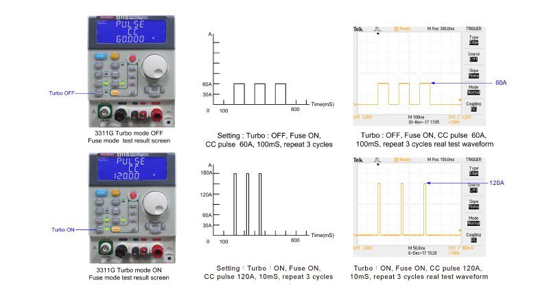
For the Non-Trip test, the current protection component is required to achieve non-blown action, so the test current needs to be lower than the fuse current specification. To verify that at normal current levels the device does not trip, the 3310G Series electronic load checks that during the test time (Pulse Time) the device does not trip after repeating the number of repeat cycles. The load LCD will display the number of Repeat Cycles applied.
4. The capacitive load and sudden hot Plug-in test of power supply at startup
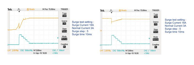
The power input circuit of the electronic circuit usually has many high-capacity capacitors, so the output of the power supply will have an instantaneous starting current when the power is turned on. The 3310G series has a unique surge current test mode, which can provide instantly up to 200% load specification current (example: 3311G continuous current specification 60A and maximum surge current can be tested to 120A) Test time up to 2000 ms, can be used to power the power supply or charger connected to the electronic circuit at boot. The instantaneous starting current of the simulated load is used to test whether the output voltage waveform of the capacitive load meets the requirements when starting up, as shown below.
In addition, when the power supply or charger is in operation, the hot plug-in electrical equipment will cause a surge load current when it is connected. The 3311G series incorporates the running surge current test function to view the electrical appliances when the load is suddenly connected, to see if the power supply or charger output voltage is stable enough. As shown below.
5. NTC simulation test (this feature is optional)
Based on the safety issues with lithium batteries and the effect of ambient temperature, lithium batteries and chargers must require a temperature protection mechanism to prevent causing danger under ambient low and high temperature conditions.
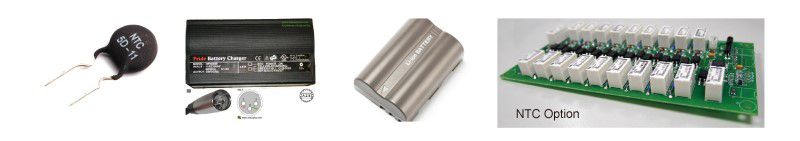
The 3310G Series electronic loads and 3302G mainframe support the NTC resistor simulator option. The 3310G Series can set NTC resistor values from 1000 to 500KΩ, equivalent to 10KQ NTC resistance for a temperature range from -46°C to +179°C. Changing the NTC resistance verifies if the lithium battery and charger temperature protection system operate correctly by either halting the charge or discharge cycle or by reducing the charge and discharge current. When the temperature returns to normal working temperature levels, the load checks if the protection action recovers and returns to the operational state, i.e. restores the normal charge and discharge.
6. Load operation mode supports CC+CV and CP+CV mode
The 3310G Series electronic loads not only include 3310F Series functions like CC, CR, CV, CP, Dynamic load mode, it also adds the new CC + CV and CP + CV operation modes.
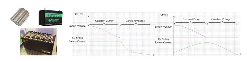
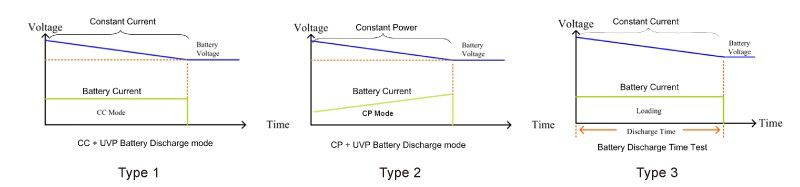
During discharge testing of batteries, special attention should be paid to avoid over-discharge. This will cause the battery voltage to drop too low and cause permanent damage.
When using the CC + CV or CP + CV mode of the 3310G Series electronic load, the battery will respond to constant current (CC) or constant power (CP) mode set by the electronic load to discharge. When the minimum allowable discharge voltage of the battery is set as the CV voltage value - the lowest voltage of the discharge test - the CC + CV and CP + CV modes can ensure the battery will not be damaged due to overdischarge, resulting in battery loss.
7. Battery test function
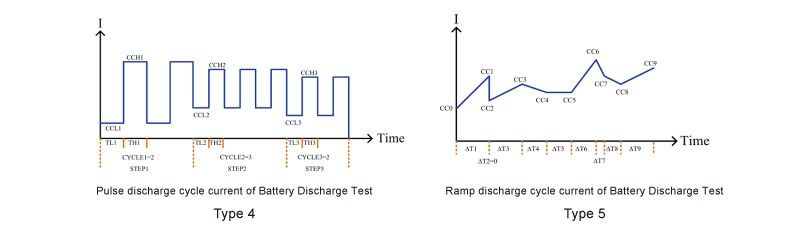
The 3310G Series load also supports five new battery discharge tests, TYPE1 ~ TYPE5. You can select the appropriate battery test mode and test results can be directly displayed on the LCD display showing the battery AH capacity, the discharge voltage value, the cumulative discharge time data etc.
There are also CC pulse cycle life test and CC Ramp Cycle life test types (Type 4, Type5 provides remote operating only). These can be used to simulate the battery in actual use by using a variety of load current changes and cycle variations. The user can verify and simulate the performance and life during actual use of batteries.
8. Battery real discharge current simulation and test
The 9923 Current Waveform Generator can be added as needed to provide battery real discharge current waveform simulation.